Title: DeFrost Fridge Electric Wiring Diagram with Timer: Ensuring Optimal Cooling Efficiency

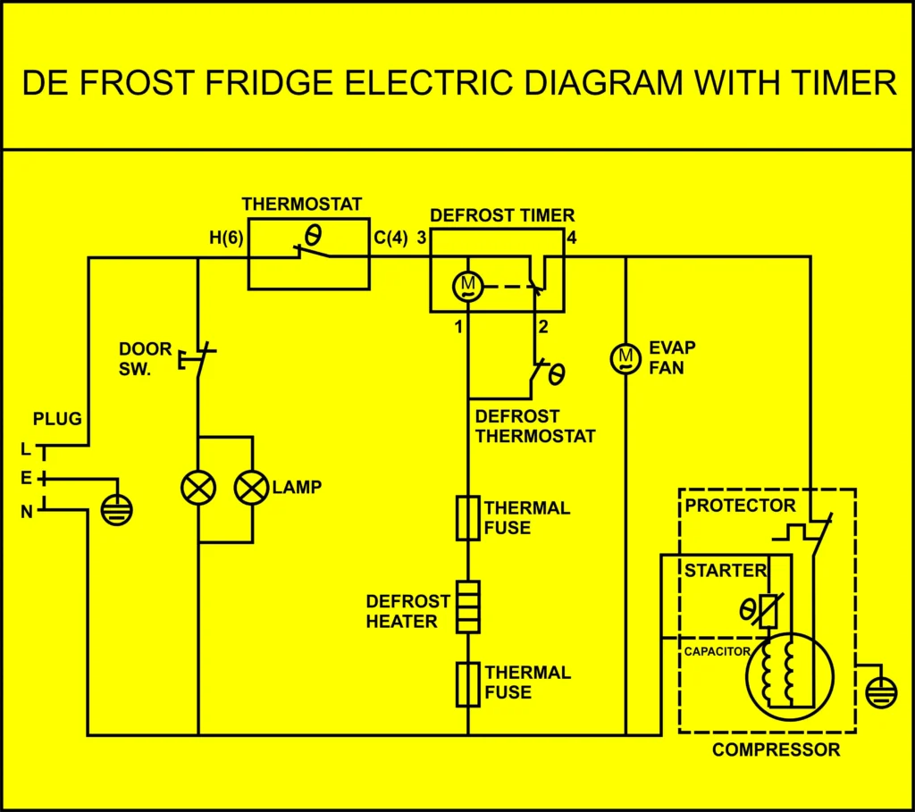
In the realm of refrigeration technology, the DeFrost Fridge Electric Wiring Diagram with Timer stands as a pinnacle of efficient cooling and preservation. This intricate system incorporates various components meticulously interconnected to ensure the smooth operation of the refrigerator, maintaining the freshness of stored food items. Let’s delve into the detailed anatomy of this wiring diagram, highlighting its crucial components and their functions.
At the heart of the DeFrost Fridge Electric Wiring Diagram lies the compressor, the workhorse responsible for circulating refrigerant throughout the system. The compressor compresses the refrigerant, raising its pressure and temperature, thereby enabling efficient heat exchange within the refrigerator.
Adjacent to the compressor is the thermal fuse, a vital safety component that interrupts electrical flow to the compressor in case of overheating, preventing potential hazards such as fires or damage to the unit.
The thermostat serves as the regulatory mechanism, monitoring the internal temperature of the fridge. When the temperature exceeds the desired threshold, the thermostat signals the compressor to kick in, initiating the cooling cycle.
Conversely, the fan plays a crucial role in distributing cold air evenly throughout the refrigerator, ensuring uniform cooling and preventing temperature imbalances.
In the DeFrost Fridge Electric Wiring Diagram, the presence of a lamp adds an element of convenience, illuminating the interior of the fridge when the door is opened, facilitating easy access to stored items.
One of the most pivotal components is the defrost timer, strategically integrated into the wiring diagram. This timer regulates the periodic defrosting cycle, preventing the buildup of frost on the evaporator coils, which could impede cooling efficiency over time.
The door switch serves as a safety feature, cutting off power to the lamp and other components when the refrigerator door is opened, conserving energy and minimizing the risk of accidents.
Last but not least, the heater element plays a crucial role in the defrosting process, gently warming the evaporator coils to melt accumulated frost, ensuring uninterrupted cooling performance.
In conclusion, the DeFrost Fridge Electric Wiring Diagram with Timer epitomizes innovation and efficiency in refrigeration technology. By seamlessly integrating components such as the compressor, thermal fuse, thermostat, fan, lamp, defrost timer, door switch, and heater, this diagram ensures optimal cooling performance, prolonging the shelf life of perishable goods. For more insights and diagrams, visit fully4world.com to explore a plethora of resources on refrigeration technology and beyond. and watch AC and Fridge repairing Videos
